1. Determination of core design parameters:
The first step in the design of a small wind turbine blade is to clarify the core parameters, which directly affect the wind energy conversion efficiency and unit stability, mainly including:
The blade design tasks for small wind turbine include rated power (KW), rated wind speed (m/s), rated speed (rpm), etc;
Tip speed ratio: The ratio of blade tip speed to wind speed, which is a key indicator for measuring wind energy utilization efficiency (usually the optimal value is 5-8). Too high will increase noise and fatigue load, while too low will reduce efficiency.
Number of blades: Modern horizontal-axis small wind turbines commonly use a 3-blade structure because 3-blades can balance wind energy capture efficiency, unit stability, and manufacturing costs -2-blades have high noise and severe vibration, while 4-blades increase weight and cost.
Wing selection: The contour line of a certain section in the direction of blade extension directly determines the aerodynamic performance. The typical characteristics of an airfoil are: the leading edge is thick and has a small arc shape (reducing airflow separation), the trailing edge is thin and sharp (reducing drag), and the surface is smooth to reduce roughness.
2. Pneumatic design optimization: improving wind energy capture efficiency
The second step in small wind turbine blade design is the core of blade design, with the goal of maximizing wind energy conversion efficiency (Cp value), which requires iterative optimization through CFD simulation and experimental verification:
CFD numerical simulation: Using computational fluid dynamics (CFD) software to simulate the flow field around the blade and analyze the boundary layer separation and stall characteristics of the airfoil. For example, by using CFD to verify the lift coefficient of airfoils at low Reynolds numbers (common operating conditions of wind turbines), efficiency reduction caused by boundary layer separation can be avoided.
Tip speed ratio optimization: By adjusting the blade length and speed, the tip speed ratio is kept within the optimal range. For example, small wind turbines (such as 100Kw) can adapt the tip speed ratio to low wind speed environments by optimizing the blade length.
3. Structural Design: Balancing Strength, Stiffness, and Weight
The second step in small wind turbine blade design is the structural design, it needs to achieve a balance between strength (wind resistance, fatigue), stiffness (deformation prevention), and weight (cost reduction), with key measures including:
Thickness distribution design: The blade thickness gradually increases from the root to the tip. The leaf root needs to bear greater bending moments and loads (such as centrifugal force and wind load), so the thickness at the position of the maximum chord width is larger (usually 30% -50% of the chord length); The blade tip needs to reduce weight and have a smaller thickness. For example, the root thickness of the maximum chord width position of small wind turbine blades (less than 100Kw) is about 30% of the chord length, and the tip thickness is about 10%.
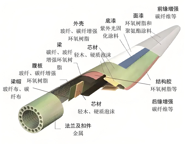
Material selection: Prioritize the use of high-strength and lightweight materials, such as:
Small and medium-sized wind turbine blade design materials: fiberglass reinforced plastic (FRP) - low cost, easy to form, suitable for manual or injection molding production;
Small wind turbine blade design of anti resonance design: By adjusting the natural frequency of the blades, resonance with the wind turbine speed or tower vibration can be avoided. For example, by using finite element analysis (FEA) to calculate the blade vibration frequency, ensure that it is far from the operating frequency range of the unit.
4. Modeling and Validation: From Theory to Physical Object
The fourth step in small wind turbine blade design is the feasibility design, it needs to be ensured through 3D modeling and experimental verification
Modeling with software such as PRO/E and CATIA: Input blade element data (chord length, twist angle, airfoil) to generate complex surface models. For example, by simulating the changes in different cross-sections of the blade through PRO/E, it is ensured that the twist angle from the blade root to the blade tip is continuous.
Experimental verification: Verify the aerodynamic performance of the blades (such as lift coefficient and drag coefficient) through wind tunnel tests, and verify the structural reliability through fatigue tests. For example, the WT2000D121 unit has been experimentally verified to have a deviation of less than 5% between the dynamically identified load and the measured results.
The above are the key points and optimization solutions for small wind turbine blade design, covering the entire process from parameter determination to environmental adaptation.
Hotline